Two pumps connected in series double the head capacity of a single pump while the flow rate in GPM or
brake horse power (BPH) remains the same as for one pump. Two pumps connected in parallel double the
flow rate, while the head capacity remains the same as for one pump.
Parallel operation is not normally used on petroleum pipelines. Pump stations are costly to operate and
require man power. The objective in pipeline design is to use as few pump stations as possible. The size of
the pipeline maintains the required volume. Pump stations are designed to push fuel products as far as
possible down the line. As a result, pump stations are connected in series.
PART D - PUMP GRAPHS
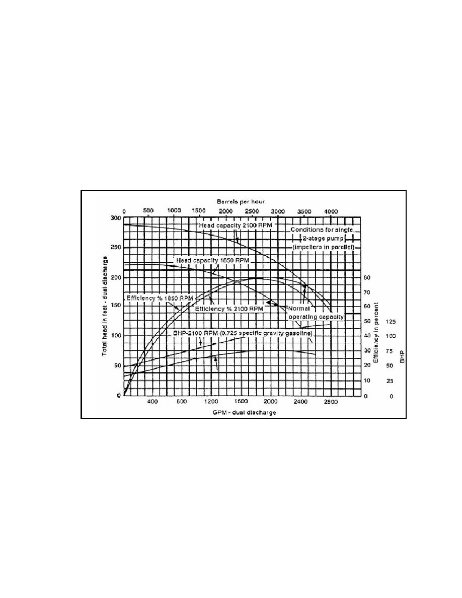
Observe how the pump graph is constructed (Figure 5-1). The graph consists of a coordinate system. It is a
uniform scale which means there is an equal space between all units on the graph in both directions. Rate of
flow is plotted along the X or horizontal axis increasing from left to right in GPM on the bottom and BPH on
top. The remaining variables are plotted along the Y or vertical axis. The RPM curve defines what is
referred to as the operating speed of the pump.
Figure 5-1. Pump graph.
Pump Graph Application. A common application of a pump graph (Figure 5-1) is its use in
determining the rate of flow, efficiency, and BHP given the total dynamic head in feet and operating speed of
the engine in RPM. Recall the definition of dynamic head--the height to which a pump can push a column of
liquid. Rate of flow is the most commonly desired variable on the graph, and it can be expressed in either
GPM or barrels per hour. At an engine speed of 1,800 RPM and total dynamic head of 160 feet, determine
the following:
Rate of flow (GPM).
Efficiency (%).
Brake horsepower (BHP).
To solve this problem enter the graph on the Y axis at 160 feet of head. Follow this line to the right until it
intersects the head capacity curve for 1,800 GPM. At this point, all answers are determined vertically up and
down.
5-3
QM 5096


 Previous Page
