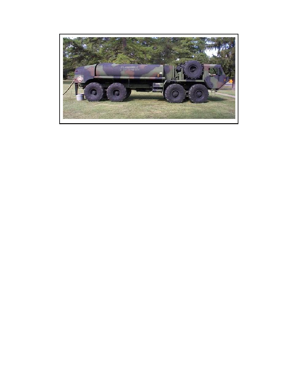
Figure 3-5. M978 HEMTT tanker.
Vapor Recovery System. The vapor recovery system can be installed on all models of tank semi-
trailers, and is required in certain ecological areas. The system allows a fuel depot to collect or recover the
vapors and gases that are present during the loading operation. Vapors can also be recycled back to the
semitrailer through the recovery system during the loading operation. This system consists of a vapor-tight
line running from the sealed hood on the emergency valve vent (directly behind the manhole cover) to the
rear of the tank. The rollover rail on the roadside of the semitrailer is used as part of the line. The adapter
on the end of the line is compatible with the 4-inch quick-disconnect, vapor recovery connections at a
majority of fuel depots.
Tank and Pump Unit. The tank and pump unit consists of a 50-GPM pumping assembly, two 600-
gallon aluminum tanks, and related equipment. The unit is designed to be transported on the 5-ton, 6X6
cargo truck, due to the fact that when the unit is filled with fuel it exceeds the load limit of the 2 ,-ton cargo
truck. The unit can be used to fill and empty 500-gallon collapsible drums, 55-gallon drums, and 5-gallon
cans; temporarily store product; refuel ground vehicles; and replace or supplement special-purpose vehicles.
The unit may also be used to fuel aircraft if no other aircraft refueling equipment is available.
There are several standard models of the tank and pump unit. The main differences are in their pumps,
filter/separators, manifolds, and hoses. TM 10-4930-204-15 (Operator's Maintenance Manual for Tank and
Pump Unit M978) gives details on installing, operating, and maintaining the different models of the unit. A
description of the various components is provided as follows:
Tanks. The tank shells have a manhole assembly, pump-port drain plug, and discharge valve assembly.
Controls for the discharge valve are on the top of the tanks. The discharge valve outlet is at the bottom rear
of the tank, and the drain plug is at the bottom front. A baffle inside the shell helps keep down the surge of
product during transport. Two lifting rings are attached to the top of each end of the shell to make handling
easier. Tie downs are provided for securing the tanks in the vehicle bed.
Pump. The pump is a 50-GPM, self-priming, centrifugal pump. The impeller is screwed on the extension of
the engine crankshaft. The engine is a 1-cylinder, 4-cycle, air-cooled, hand cranked engine. Some models
have 2-cylinder, 4-cycle, overhead-valve, air-cooled engines. A radio-shielded magneto supplies the ignition
spark, and a governor controls the engine speed by varying throttle openings to suit pump loads. The
gasoline tanks hold one gallon. The pump and engine are mounted on a common base so that they can be
easily removed for servicing and can be used in other pumping operations.
Filter/separator. The filter/separator is a vertical, 50-GPM capacity unit with four standard canisters and
filter elements. The tank and pump unit can be used to refuel aircraft because the filter/separator qualifies
under military aircraft refueling specification.
Manifold. The manifold controls the flow of product to the suction side of the pump. Two quick couplers
provide connections or inlets for the tank suction lines. The product flows from either or both tanks to the
pump suction through the manifold outlet and a section of hose. Some models have a discharge hose that
3-7
QM 5098


 Previous Page
