profile starting at 200 feet elevation on the left and ending at 1400 feet
elevation on the right.
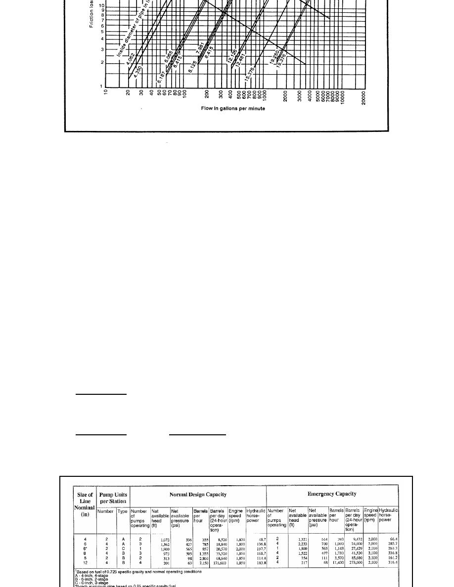
Figure 3-1. Head loss due to friction.
Determin+e the Hydraulic Gradient: To determine the hydraulic gradient for
the chart, multiply 97 ft/mi by 10 miles = 970 ft. Locate 10 miles on the
bottom horizontal axis and 970 ft on the left vertical axis. Draw a
straight line between the two; this establishes the slope of the Hg. Find
the total head for a 6 inch pipeline 1362 ft/hd (Figure 3-2). Using the
hydraulic gradient as a guide, draw a parallel line from 1662 ft/hd down to
the pipeline trace at 950 ft/hd at 7.5 miles. This is your True Gradient.
From the True Gradient back up 64 ft of head to meet the minimum requirement
of 20 psi at each pump station. Using the hydraulic gradient as a guide,
draw a parallel line from 1598 ft/hd down to the pipeline trace at 900 ft/hd
at mile 7. This is your Design Gradient. We will locate pump station 2 at
this point. At pump station 2, draw a vertical line up 1362 ft/hd, now draw
a parallel line down to the pipeline trace at mile 22.75 and 810 ft
elevation. This is the location of pump station number 3. Simply continue
this procedure to place the remaining pump stations. The end of the profile
is the Head Terminal (HT). From pump station 4, you can see that the line
does not come in contact with the pipeline trace, at this point there is a
terminal and the fuel will enter the terminal at 1190 ft/hd or 373 psi. Use
the formula shown below.
Where:
P = pressure, in psi
H = head, in feet
SG = specific gravity
(h) (SG)
P=
or
P = (0.433)
(h) (SG)
2.31
and
(2.31) P
P
h=
or
h
=
SG
0.433
(SG)
Figure 3-2
Operating characteristics of standard pipeline pumping stations
12-31
QM 5099


 Previous Page
