INTRODUCTION
It is very important to fully understand the layout and design of a
petroleum pipeline for effective and safe movement of fuel. As a result of
this instruction you should be able to apply the basic principles to plan
and design a petroleum pipeline.
PART A HYDRAULIC GRADIENT
Placing Pump Stations Using the Hydraulic Gradient: Although you will not
be required to place pump stations while you are here in the school, it is
very important that you understand the principles of how it is done. Given
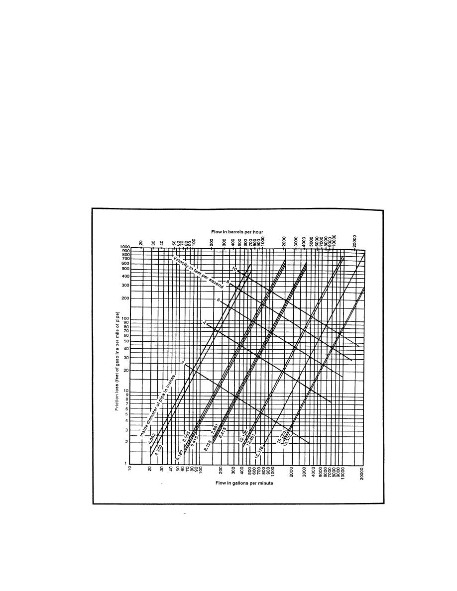
a flow rate (Q) of 600 gpm, Mogas at 60, F and a pipe diameter of 6.415
inches, we can determine Hf = 97 ft/mi (Figure 3-1). This chart is
constructed to show miles on the horizontal axis starting at zero on the
left and ending at 80 miles on the right hand side of the chart. The left
vertical column shows elevation in feet of head starting at zero and ending
at 4000 feet of head. The pipeline trace is represented by the ground
12-30
QM 5099


 Previous Page
